2. Basic knowledge
2. Basic knowledge
Definition of Hole Cavity
All types of holes in an integrated block are called cavities. A single hole cavity may be a drilled hole, a plug hole (SAE port, BSP port, NPT port, etc.), a cartridge valve cavity, a bolt hole, and a locating pin hole. Orifice cavity multi-hole is a combination of single holes, divided into plate valve holes, flange holes, common combination holes, two-way cartridge valve holes.
Orifice cavity step
The profile of an orifice cavity is made up of its step size and the number of steps. Where each step is made up of a cylinder and a cone, the step information is similar to a drill with a drill diameter, a drill depth and a taper angle at the bottom of the drill.
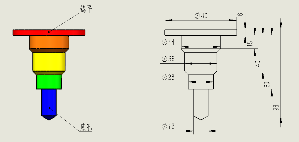
Note:
- if there is a countersink step, the depth reference for the later steps, except for the bottom hole (the last step hole), are referenced to the bottom surface of the countersink.
- all bottom hole depth dimensions (last stepped hole) are referenced to the surface.
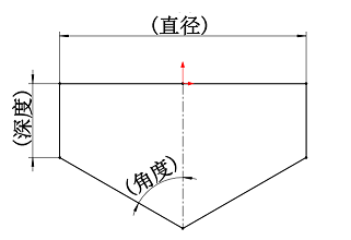
Note:
- when the angle = 90°, it is the bottom of the hole is a flat bottom.
- when depth = 0, then the profile is only angular.
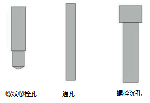
Bolt hole
Three types of bolt holes used in valve block design
- Threaded bolt holes (for mounting parts on the block and for mounting the block) - metric or imperial threads can be used
- Through bolt holes - can be drilled directly through using "Drilling
- Through bolt holes with countersunk holes (for mounting blocks) - available with "Through bolt holes
Definition of slant holes
For compact blocks with a minimum number of cross holes, the usual viable option is to use angled drilling. TouchMDesign software can model and visualize angled holes as well as drill them.
The α-angle is the angle of rotation of an angled hole on a surface.
Angle holes with 0, 90, 180 or 270 α angles are called simple angle holes.
Angular holes with an angle other than 0, 90, 180, or 270 are called compound angular holes.

Beta angle (Beta) is the angle hole that is inclined to the surface normal.
The α and β angle values are entered in the Edit Hole Cavity dialog box.
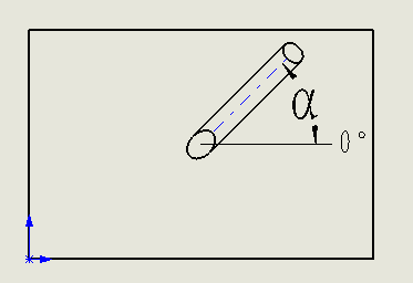
α - rotate on the surface
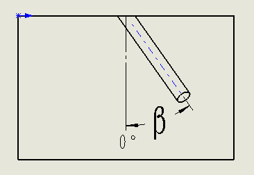
β - angle normal to the surface
Each view uses the α angle convention
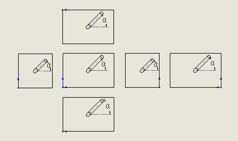
**Note: Angular hole depth is the depth along the axis of the angular hole. **
Definition of hole cavity position reference
When inserting a hole cavity, the position of the hole cavity needs to be defined. In TouchMDesign software, the following types of hole cavity positioning reference objects can be selected
1. point - any sketch point in space, any entity vertex in space, the midpoint of the entity edge
Binding relationship: the hole cavity center positioning point will be aligned with the selected reference point, overlap or XY direction or marked with the corresponding distance.
2. Straight line - any sketch line in space, any solid edge line in space
Constraint relationship: the center of the hole cavity will be positioned with the selected reference line, overlap or marked with the corresponding distance.
3. Arc - the arc edge of the solid contour of the hole cavity
Binding relationship: the center of the hole cavity will be positioned with the selected reference arc, concentric or coincident or marked with the corresponding distance.
4. Face - the cylindrical surface of the hole cavity contour
Binding relationship: the center of the hole cavity will be positioned with the selected reference cylindrical surface center axis, concentric or marked with the corresponding distance.
Note: The selection of the above bore cavity positioning reference objects, please combine reasonably according to the design intent, will help improve the quality of the valve block design and the speed of adjustment
Simplicity in processing of hole cavity contour dimensions
- Simple display of cavity contour dimensions
- Avoid the visual distraction of unnecessary dimensions
- Easier and more convenient to modify dimensions
- Clicking on any cavity will quickly display the diameter and depth of the cavity, making it easy for the user to make quick changes
